Weather | Buy&Sell | Forums |  |
Weather | Buy & Sell | Gallery | Forums | |
cleaned the bead blasted FF28 with hot soapy water, then brake cleaner, the hot soapy water, then brake cleaner. Dumped it in the anodise tank. This time tried Waricle's idea of using welder to supply the DC. On startup the voltage was about 2v @ 30 amp and the voltage slowly climbed and the amps dropped over the next 15 min to about 6v and 22amps. (the knob didn't seemed to do anything but that probably means I haven't read the manual)
After 15mins welder switched off so I switched to the batteries as was the plan...I originally thought welder had overheated. Oddly, I only got 7amps now on batteries when previously I got 65amps. Slowly, after draining both batteries current got back to about 50amps (at 10+volts at the electrodes) and all the jumper cables started melting again. Turns out the welder shut off because of one of those protection thingo's in a 4 way I'd plugged into. Plugged the welder directly into a 15amp supply so any shut off would be welder, not supply.
The new coolant system was working well and keeping temps steady but I then ran out of ice and temp started climbing. Batteries died so switched back to the welder just as temps hit 39degC. The welder could supply about 6V at 22Amps, chiller looked liked it could maintain/decrease temp at this load and welder seemed happy so left it run a few hrs. Had to change the coolant water every 30mins to fresh tap water (25DegC) to maintain control of the temps. There is 2.3m of 10mm, 1mm WT Al tube in the tank and ran the 12V pump sub optimally by mistake at 10.3v...so increasing and flow and more ice on hand should allow much better handle on temp control at high power in future.
Pulled the fin after 4hrs, rubbed all the black goo off and chucked it in the dye tank. Dye uptake is nowhere near as expected for a commercial dye so will leave over night and if still nothing tomorrow water will throw in turmeric bath as know this works.
Regardless of outcome next step will be to try and anodise standard Al to get ready for cnc'd version.

To be honest the pie was a Mrs Mac's standard beef that had been sitting around for too long (Shoulda gone with their burgers)...however, the cafe owners recognised me and have survived the last 15 years and they keep the most interesting/useful machine/manufacture sector in Perth fed all within walking distance so it was hard to complain. There is even an anodiser next door as a backup plan for the CNC fins and all sorts of other interesting stuff.
I printed the "flex" gasket and fitted it to the FF18V4...alas it was completely different to my cast. I see the problem, the cast I have is FF18V4_389 when the design sent to the CNC and what the gasket was designed around is FF18V4_V4. Fangy specifically said not not worry about the revision numbers but you can see the fin mount from 389 (first pic) to V4 next pic has moved a good 30mm. So the revision number is important.
However the 3D printed gasket whilst super flexible I think is not compressible enough for intended purpose..maybe some neoprene rubber is a better option.


Flex I don't think you need a compressible material, I use a relatively hard plastic with my FF and it works well. It's mainly to protect the board
Stroppo put us onto a workable solution.
Tube of marine Sikaflex PU.
All you do is apply a release agent to your board around the fin box slightly larger than where the fin will contact.
Put some of the sikaflex on the bottom of your fin where it will contact the board.
Pull the fin down to "almost" the full setting (ie leave about 1.5-3mm) let it cure.
Remove fin (to make sure it has released from board)
Replace fin, Tighten it down, the Sikaflex should bulge out a bit, trim accordingly You may wiish to have some plastic tape applied tp your board first as a cutting surface.
Job done, if it eventually dies just repeat.
If the fin is used on multiple boards with different rocker lines around fin area and this creates an issue, just do it in the front and rear portions of the fin or just set it to the one with the bendiest rocker.
Word of warning unless you are going to use a lot of this then only get the squeeze tube as the stuff has a shortish shelf life once opened.
Glad Wrap as a release agent works well, and in my experience( which I only realised the other day, amounts to 100's now![]() ) just about any bathroom/gutter silicone sealant works well enough, just be aware of the set time which can vary quite a bit. I think I have used just about every brand and while Sika is the best, I am not sure its that much better to justify the cost rather than the cheap stuff. White looks the best new but Grey ages the best. I would suggest whatever you have lying around will be fine. I have not ever had a tube go hard on me, but I get through the stuff a bit more than most.
) just about any bathroom/gutter silicone sealant works well enough, just be aware of the set time which can vary quite a bit. I think I have used just about every brand and while Sika is the best, I am not sure its that much better to justify the cost rather than the cheap stuff. White looks the best new but Grey ages the best. I would suggest whatever you have lying around will be fine. I have not ever had a tube go hard on me, but I get through the stuff a bit more than most.![]()
Just thought I had better post a photo of what I am babbling on about finish wise. This is a slow and low 'clear' anodised fin. The fin surface was finished to #120 grit prior to anodising. Post anodising, lots of the scratches have filled in.Yay! I gave it a rub with #400, but it's bloody hard so I am not sure I made much diff in overall smoothness. The dark grey is contamination of the anodised layer with the silicon. (used in casting alloys to help them flow). The spots, I think, are spots of higher magnesium and perhaps silicone as well. To touch it feels very smooth, defo much more so than it appears. The spotted gun metal finish is starting to really grow on me now and I am keen to see how they fare in the wild.


could waffle on about stuff discovered today but end result was Dylon Ocean Blue dye just doesn't work in the slightest despite overnight soaking. Turmeric and RIT Fuchsia (even after dye left for 6+ months) work well. Turmeric suffers that you need to keep agitating it. Current aim is to master standard anodising to prepare to the CNC fin as seems little point to attempt a cast Ano unless can do normal ano first.
Did some coupons today out of 10mm dia Al offcuts from the chiller, they took way more amps at full 12+Volts than I was expecting...10+ amps. Their surface area is almost exactly 10 times smaller than a FF18V4. 12V is supposedly the min recommended anodise voltage so need to try two batteries in series as the current load at high amps with a fin makes a large voltage drop across jumper cables and drops the supplied voltage at electrodes to around 10V best case if using just one 12V bat. My welder can not deliver a high enough voltage but Fangman's fancy adjustable power supply that can keep a higher voltage but fiddle with amps to control heating is the better approach. Since I can't control current with a couple of batteries I will try the fast and furious approach.
initially soaked coupons in the Dylon blue dye but similar to the FF28 zero uptake after 30 mins so dropped them in the RIT dye (that had sat around for 6+ months). After 30 mins in dye they looked perfect and little difference between sanded and raw..(top two cm where the holes/wires are was unsanded) After 4+ hrs the colour was deeper but had some discolouration in tiny section on both coupons..so dye time optional between these two. One coupon had NaOH treatment (one with extra drill hole), the other had nothing and little difference between them. I purposely tilted the coupons in the ano tank to see if any variation due to current effects. Next attempt will be to try normal Al with same surface area as a FF18V4 = 98999mm^2 to try and get uniform anodised surface. If can't do that then will farm out ano for the CNC fin.
For the surface area of a FF18V4 this should make the current draw at 24-26V around 117amps and the supplied voltage at electrodes around 4.3V less. This continuous current is going to melt standard jumper cables so will need to double them as bare min. 117 amps at 22V is 2.5KW heating which is going to boil 11 litres of acid from zero deg C in less than 30 min. Can't go above around 40degC acid temp to so will get 10 min plus what ever chiller is capable of. The chiller roughly seems to extract about 140W using 10degC temp difference so best case might get 300W chilling using near zero degC water giving 2.2KW overall heating. This gains a whole 2 min. extra or 12min total. It seems pointless other than the fact I need it to initially chill the acid. If I start at 25degC acid temp I will get tops 4.5min before acid overheats. Batteries at this load should deplete within 10 min assuming something else doesn't melt. Supposedly there is the law of 900 where time to anodise = 900/amps * square feet to be anodised *1.2. For the FF8V4 this is 9.2 mins which is right at the limit for batteries and chiller. The FF28 should have higher currents and problems so seems like will have to do it in two stages..the way this is all going it seems the CNC and farm out anodise is going to be the preferred solution and all this is just light entertainment.
Photos
#1 is anodised coupons after 30 mins in RIT Fuchsia dye (and 30+ mins in Dylon Blue no effect). Right coupon has NaOh bath
#2 is around 4 hrs, left has the NaOH bath
#3 Dylon dyes..they 'look' great but no effect
#4 RIT Fuchsia after long time sitting around
#5 FF28 after a few hrs in turmeric, too patchy so resanded
#6 FF28 after heavy 400 grit sanding..still plenty of turmeric


Wow I blinked & lots of stuff happening does this mean there will be an option to order colour coded fins to match our gear, or will it be different sizes like the coat hangers when buying shirts so easy to work out what size in a hurry when rigging?
Or will I just be able to tell how deep the razor scratches are by the colour of the surface![]()

On the subject of gasket performance on Fangys my biggest improvement was to discard flexible washers on the fin bolts. In particular the front bolt as the large overhang and the slight compression of a flexible washer opens the gap at the front enough gap to allow weed to enter. That gappiness will definitely spoil your happiness when the fin bottoms out in thick weed.
Looks like progress is being made on the anodising front too, well done fellas.
Bit of an update.....weird/very unexpected results...
I upgraded my cheap arse jumper cables to proper 200+Amp wires, shortened them to min length and wired my two batteries in series to give 24V. Cut some Aluminium I had lying around to the exact surface area of the FF18V4 which I have both in cast and soon hopefully to be CNC format. Bought a few bags of ice and started chilling as much water as I could to pre chill acid...was about to hook it up when a pile of life stuff happened all at once which required attention/sorting out as priority. (not sure why but everything always seems to go wrong at the same time despite being completely unrelated)
Ultimately this gave me some time to think through what I was about to do and I started getting cold feet. The first issue was the sheet was roughly 1/3 the tank size and to cut down on Al wire used I'd put it near the top of tank. (see photo) Trouble is, having the sheet at the top will mean heating the acid at the top 3 times quicker than previous calculation so will get just over 1 minute before my 0 degC acid becomes about 40degC. I could run longer Al wires so the sheet is at bottom but this then introduces the issue that the whole sheet can move by convention currents (sheet is only 0.5mm thick) and short circuit to lead sheet.
The next issue is running my batteries in near short circuit condition at 120amps continuous may not do them any good. That is the least of the worries though...this is essentially a 1.2KW+ hydrogen + O2 generator and to start the anodising I have to connect jumper cables that will deliver a 120amp+ spark. The first spark should not ignite the H2 O2 since the spark comes before gas but it will no doubt weld the clamps to the aluminium. The issue is the disconnection. If I need to disconnect then best case there will be massive sparks and will ignite the H2 O2, worse case the clamps are welded and trying to free them will almost certainly result in shorting the battery connections and more sparks. Hmmm, what could possibly go wrong?
All this is probably fine if I could somehow do it remotely. I do have some 1000V, 1000amp contactors lying around which is fine for the initial start but they will definitely weld in the closed (on) position if trying to disconnect under 120amps DC so they are essentially useless. (switching DC under load is hard) That means I have to do it manually in a H2 O2 atmosphere right next to (hot to maybe boiling) sulphuric acid with connections that are probably welded.
So I started thinking Fangman's slow and steady approach is probably wiser and started looking into power supplies...There is some nice DIY kits capable of 50V at 8amps but the cost of parts was approaching $200, will takes weeks to arrive and then still have to build etc....thinking ahead I need 2 of these for hard anodise system.. not really worth the investment.
Luckily one of the 'life' issues I needed to attend was my hot water system failed and that meant I had to move some cheap arse Ebay solar panels I had bought 15 years ago so the plumber could gain access. It suddenly dawned on me this was (maybe) a far better solution for an adjustable DC power supply. Need more voltage, just stack panels in series, more current, stack them in parallel, adjust power on/off with a blanket etc covering panel.
Open circuit voltage of 1 panel was 20V and I think when I purchased they claimed 100W, which means about 80W in Perth sun. Hooked it up on ano tank with the dummy FF28 sheet and got 8V at 5 amps so about 1/2 the claimed power. Need more than 12V ideally for ano so tow should do the trick. I hooked 2 panels in series and got about 15.5V at 6.5amps delivered. Seemed nice..there was a satisfying buzzing anodise sound and nice bubbles.
After 10 mins came to check and all was well but in the space of a few seconds doing nothing the voltage climbed to 33V, current dropped to 3.7amp and the noise stopped. Within 30 secs the voltage dropped back to 17V or so and current back to 6amps or so and the noise resumed. What the?
For the next 20 mins or so looked steady state and from the rule of 900 at 6.5-7 amps figured standard ano time was in the order of 2-3 hrs. (i.e. 900/7amps * square foot area to be anodised X 1.2 = time in minutes) 1.2 is min current density. A FF18V4 = 1.06 square ft surface area. Had offsite task to do so did that and was away for no more than 80 min. There were zero clouds in the sky and I'd chucked the panels on the roof so no interruption.
Came back and found all the Al wire eaten away and the system running open circuit. weird, I'd run system at 50+amps 10V with just 2 or 3 Al wires and never eaten. Here was 6 amps at just 5-7 volts higher and 9 Al wires were eroded away. I chucked the sample in the dye but as expected no uptake after 4hrs, meaning no anodise layer. The dye for sure is great way of confirming a successful anodising.
Need to try again and witness what is happening and see where it went pear shaped.
Despite cleaning this 6061 sheet with caustic soda for nearly 30 mins, with 2 caustic bath changes and 3 hot soapy scrubs there was still an amazing amount of 'black goo' coming out in the acid tank.
Photo#1 the sheet of Al wired to accept lots of amps and cleaned in NaOH bath for crazy amount of time
Photo#2 solar panel setup (put panels on roof to avoid shadows etc)
Photo#3 acid tank with all Al wire eaten
Photo#4 in water bath showing Al wires all eaten
Photo#5 still a pile of black goo after anodising a very very thoroughly cleaned piece of 6061 sheet (shot is bottom of acid tank after drain acid)
PS re: the Carbon nano tube experiment in pizza oven, I downloaded the actual paper and turns out I did three things wrong. First, need to clean the surface of the Al...they seem to use Methanol and NaOH, Second, the coating of NaCl or Baking soda needs to be extremely thin and water based (not chuck it on like I did), just need a few Na atoms as catalyst, third, to grow the nano tubes they need an environment of CO2 + C2H2...the pizza oven is probably Co2 rich but need to add C2H2 (acetylene) which is of course highly flammable...easy enough to make/buy but need to make a little oven to put in the oven to control the environment...Seems a second best approach is to coat the Al in carbon nano tubes....easy enough to buy but many companies making this stuff seem to offer small (10g) samples for free so have requested a 'free' sample...lets see


Interesting and as always thinking outside the box Flex. I had the same problem with my wires being preferentially attacked. The hot acid scenario just smashed them. I don't know if there is more to it, i.e. high current flow, and the physical, electrical and chemical behaviour of wire alloy versus casting. Noted it happened on your high quality Al piece too.
I only solved the problem by keeping the top section of the fin and wires clear of the bath and/or using SS fin bolts straight from my bus bar into the fin itself and not immersing anything above the level of the fillet. Regardless, you would be expecting the wires to be made useless by a thick anodic coating, not being eaten away...why is the sulphuric acid reaction on the wire aluminium so aggressive, even if it is of a slightly different alloy composition....curiouser and curiouser.
The black goo is also a mystery that keeps on giving. I though it must be a sulphur based compound, but I can't figure out the chemistry that gives a black product. I am wondering if there is some other impurity in the water/acid bath that I haven't thought of.![]()
I am still playing around at the very low end of the scale. I am trying to find that current density point where etching becomes 'electropolishing' and then the next level current density flips the process to anodising. Who knew acid and electricity could be so much fun?![]()
Another day, and more interesting stranger stuff from 2022's toy of the year (even though only emulating such a thing, not actually playing with it).
Flipped the FF18V4 sized sample 90deg (because was tight fit in tank), NaOH bath forever and whilst doing that chill'd the acid. Probably a mistake putting another variable in the mix but was interested in how cold I could get acid. Only had the infrared thermometer which is misleading as it only reads surface temps and with vapour can get all sorts of weird results...i.e. chilled water was 1degC, upon circulating through 25degC acid, chill water went to -4.5degC, Acid went from 25 degC to 10 degC in a few minutes..just not possible so the infrared thermo is not a good indicator...need to put a stainless thermometer inside the acid to get reliable reading. Take away: the acid however was definitely cooler on starting..just not real sure on how much cooler.
Hooked 2 solar panels in series like yesterday (open circuit 37+V) but got less than 8V at 6amps in the ano tank on super cleaned FF18V4 sized sample. eh? (yesterday got 15+V). Day was exactly the same as last with no clouds...didn't measure the incident radiation yesterday but today it was 577W/m^2 at start and around 600 at end. Pretty sure near identical conditions though. Same acid, same panels, same everything except a few deg cooler acid
The measured voltage was on solar panel side which eliminated dodgy connections to the anode/cathode. You would expect a dodgy connection to show as high voltage on input and no/less current. The actual measurement was good current and low voltage. Since good/same/max current of solar panels at 7amps this implies good electrical connection. Briefly checked open circuit voltage and was 37V. I'd also woven the Al wire through sample so 'should' have been much better conductivity. Wriggled/played with the connections to anode and cathode but voltage stayed 8V and dropped over the next hr to around 7V.. 6.5-7 amps throughout
Wriggled the sample slightly at 1hr 20 min and bammm..voltage now 18V and way more ano action, sound/bubbles etc. Amps throughout remained as before at around 7amps. The sound gives the impression that its eating stuff...Please correct me if I'm wrong but a better electrical connection from panels to cathode/anode should yield a higher current and lower voltage...not steady current and higher voltage. 20 mins later doing nothing then whole system did the same jump as yesterday to 33V for 30 secs No noise/low current and back to 18V. 20 Min later from this event noticed all but one of 4 Al wires had been eaten so stopped and pulled sample, rinsed and chucked in dye. Had reasonable dye uptake meaning ok ano but nothing special
Washed dye off the FF18V4 impersonator in 1 second in ultra low concentration NaOh bath...However, the remaining Al wire that had not been eaten had superb dye pen even after this caustic bath. Since this was remaining wire holding this implies need the amp density to give good anodisation.
Conclusions from todays efforts:-
0. Need to achieve conditions of whatever the remaining drive wire had. This is way higher than 6amps for a Fangy sized Al
1. Completely illogical voltages as you would expect dodgy connections to give higher voltages measured, not lower.
2. High(er) current density gives/seems to give best ano result
3. Highly suspect lead is 'another cause' of black goo. It settles quickly at bottom of tank
4. Possible: Once above 10-12V most of the Al wires dissolve, have never dissolved at low voltage (<10.5v) and high currents.
Based on that:
A.Will switch to Al cathodes and see if any goo comes from Anodising Al with 6061 Al as anode and cathode
B. Will run 2 (or more) panels in parallel for more current less voltage
C. Will keep acid at around room temp (25 degC )
Photo #1 3 of 4 drive wires eroded. Main wire closest to source power not effected (zero erosion)
Photo #2 Dye uptake in sample but was far less than optimal anodise conditions..did not seal anodised layer
Photo #3 Washed in dilute caustic bath for less than 1 sec....near perfect dye remains in remaining drive wire
Photo #4 The 'black goo' is very heavy and very lead like....so it is lead?


So you've really got me thinking now! That voltage current thing is crazy!
Where are you measuring current, same place as voltage, at the collectors?
The collectors are basically a current source, so off load voltage should be high.
Weird thought, can you have a battery type action happening in the tank, that's affecting voltage? May be a bit of +ve feedback involved, and it;s oscillating on and off. I've no idea how this could happen. but what's going on with the collectors just sounds impossible.
So another thought. If it is a true current source, the varying the resistance won't affect the current much but will affect the voltage. So here's an experiment, chuck a variable resistance in series, and see what happens. I predict the voltage will vary more than the current.
If that's not the case, then has it something to do with those disappearing wires?
Strange the one closest to the supply line is hardly affected?
Decrepit, ya measuring the current with clamp meter close to anode...it should not matter, anywhere in the circuit the current should be the same. Measuring voltage as close to anode/cathode as possible. I have no clue what was going on but the sound probably would help in analysis...at between 16-18V the sound was almost like fingernails on chalk board. Voltage higher or lower sound would disappear. Since I couldn't control voltage (bit jealous of the Fangman's setup) so just observed.
Anyway, todays test was with Al cathodes (get rid of the lead to see if that is the source of the black goo). I also added 3 temp sensors in stainless thermo wells to better understand the temp gradients in the acid tank and coolant tank (and see how accurate my infra red gun is). Was going to hook a pile of solar panels in parallel to get higher current when thought this was pretty much the same as the battery. Since the drive wires eroded only at voltages above 12V (probably above 16V) and best result so far has been with battery at voltages 12V and below, thought I'd try that before playing with various combos of panels with higher volts. i.e. todays test was lead vs al cathode at 12 battery power. (and eliminate the weird voltage stuff going on at higher voltages)
Regardless (and I was in two minds to do 12V or 24V) Instead of Al wire I riveted large bars of Al from main busbar to another bus bar riveted to sample. Overkill completely in this case.
My caustic bath was getting extremely weak and I'd run out of more, plus all shops closed today so only did a very superficial clean of the fake fin prior to dropping in the acid. Started chilling the acid but immediately saw the stainless thermowells were reacting vigorously to the acid...must be made of cheap stainless as been using my good stainless cookware to load acid with no reaction. So only chilled acid to about 18degC before starting.
This time I'd bolted the anode (dummy fin) to the bus bar and alligator clamp to the battery..the logic being H2 is light and rises so as long as battery/alligator clip below the H2 event horizon any sparks from connect/disconnect should not ignite..this been successful so far in not blowing myself up. An absence of further posts might mean I was wrong here.
Start current was about 30amps at 12.2V (about 2V higher than lead cathode result) and slowly current increased to about 49amps at 11V at end. Ran each battery about 16mins as law of 900 at this amps said need about 32min for good anodise. Very nice as batteries just capable of delivering this. Acid started at 18degC and ended at 29degC. Could have dumped more ice to keep temp lower but seemed no point.
Short result: Good anodise but more importantly....NO BLACK GOO! Acid was crystal clear. The worst black came from the stainless thermo wells. Need to loose those or at least put those inside sealed Al tubes in future.
Dropped in dye for 2+ hrs then, steamed result for 15 mins then boiled whilst cooked dinner. Not perfect but considering very dodgy clean at start some progress. Should steam way longer than 15 mins as dye still can be rubbed to some extent with finger at this stage.....Whatever, don't touch until layer is sealed.
Photo#1 Stainless thermowells, one at top and one just below midway in acid bath (Another out of sight behind in chill tank)
Photo#2 measurements at finish just before stopping after 32 mins. Volts and amps hopefully obvious, Temps from bottom is chiller tank, mid way acid , top acid
Photo#3 black goo from stainless thermowells is most of goo
Photo#4 out of dye (2hrs)
Photo#5 after steaming about 15min
Photo#6 boiling in the paella pan whilst cooking dinner
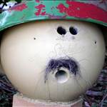
not sure what all the meteors are...and the sort of eye look..both sides are identical as far as the 'eye'. Seems to be a steam effect. The scratches are most likely me trying to agitate dye bath...need to automate this


Another question Flex, how do clamp meters work with DC?
You need AC for induction to occur?
This must be a new thing, in my day I never came across a DC clamp, I guess it must be sensing the magnetic field?
Just a quick note on the sealing. Using a Nickel Acetate solution allows to have the bath at 80 degrees and cook it for 1 min per micron of coating. (15-20 mins) When I run out of the stuff I am not sure I will get another batch, because in practice, I use a cheap immersion heating element in my tub, heat it up, drop in the fin, wander off and do something else, forget about it entirely and boil the bejesus out of it until I remember to go back and turn it off a few hours later.![]()
Low and slow results. This is a FF18V3 with 'clear coat' anodised and sealed. The surface is smooth to the touch - I wonder whether the boehmite formed during sealing fills some of the pitting defects?

I left the test coupons in the sun for a week or so that had been dyed with RIT Fuchsia. Definite fading going on as per picture so I searched for some 'proper' non fade ano dyes and came across Caswell. For the Aussies at least this (website) is a local supplier and they sell ano kits, power supplies and dyes. The dyes look 'very nice' but the dilemma is it appears it might be cheaper to go CNC/professional anodise finish for a few offs versus the cast/DIY approach. This is certainly not a given at this stage though.
The video on the below link is a bit old but really good info and piles of stuff I'm doing wrong. The book they reference seems good but at $185 and not much cheaper on amazon you need to be keen to get.
www.caswellplating.com.au/store/store.php/categories/anodising
That said, this Fangy fin has taken me down so many rabbit holes its not funny and all of them are amazingly rewarding but probably way off topic...as an example of trying to solve the Fangy cast problem (to coat with a nice pure layer of Al) I came across this guy